Generally not, you can contact our business personnel.
Real-time kinematic positioning (RTK) is the application of surveying to correct for common errors in current satellite navigation (GNSS) systems. It uses measurements of the phase of the signal's carrier wave in addition to the information content of the signal and relies on a single reference station or interpolated virtual station to provide real-time corrections, providing up to centimetre-level accuracy (see DGPS).[1] With reference to GPS in particular, the system is commonly referred to as carrier-phase enhancement, or CPGPS.[2] It has applications in land survey, hydrographic survey, and in unmanned aerial vehicle navigation.
There are UBLOX F9P, M8T, UNICORE UM482, UM980 etc.
To use standard RAM mount.
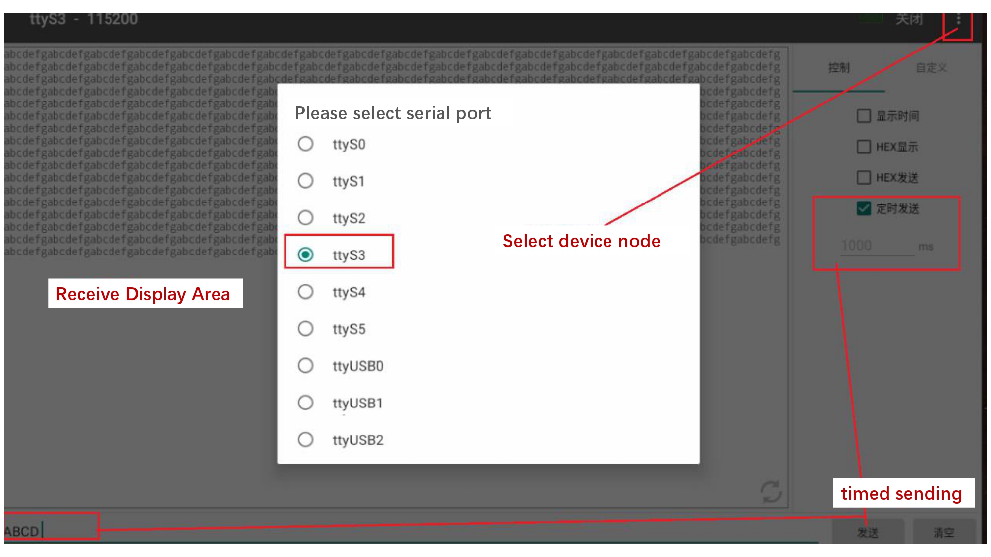
Step 1, as you can see from the 23PIN definition, 23PIN includes 2 sets of RS232, as below:

Step 2, open the built-in serial port test tool, select the corresponding software node, and confirm that the RS232 test harness sent on the PC is connected normally, and you can test it. (Scheduled transmission can be selected on the PC, and received on the T10 device side.) Select Timing Send on T10, and the corresponding information will be received regularly on the PC)
Step 3, Select the corresponding node, confirm the RS232 connection and the node correspondence, and then test the different RS232 interfaces.
Step 1, as you can see from the 23PIN definition, 23PIN includes 2 sets of CAN, as below:

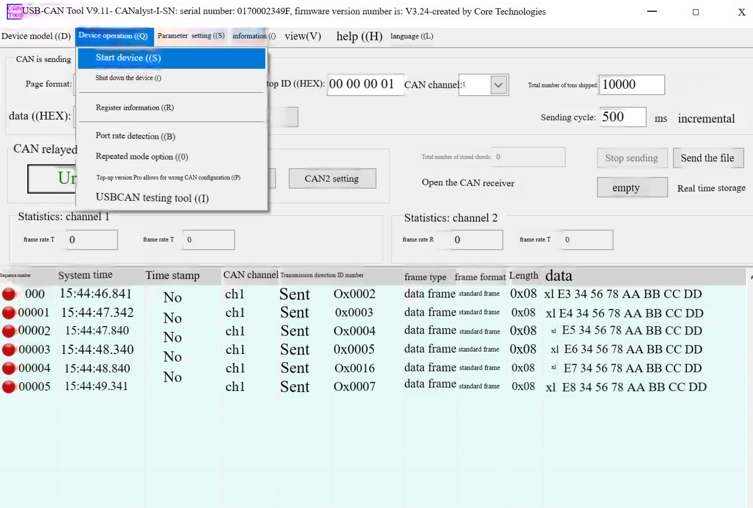
Step 2: Connect the USB CAN box to the corresponding CAN and confirm that the 120 ohm resistor on the CAN box is matched correctly. Open the corresponding CAN tool on PC and ANDROID to test.
The USB CAN box tool of Chuangxin Technology is used on the PC, and the software is usb-CAN Tool v9.11.
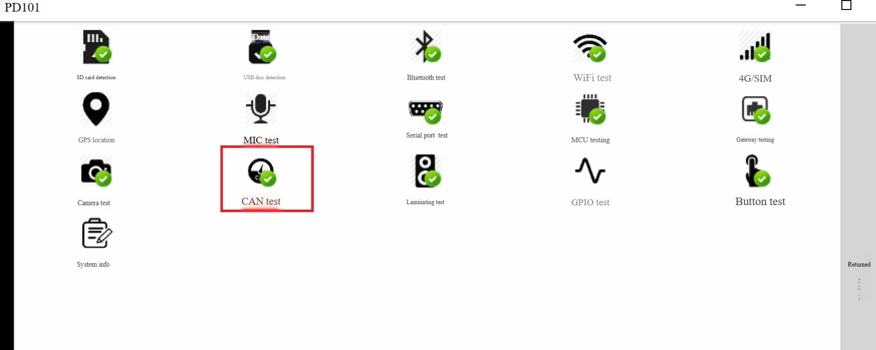
Use the CAN test function included in our PCBA test tool on ANDROID, as below:
Confirm that the CAN cable is connected correctly, set the corresponding node and CAN rate on the PC and the software on the ANDROID, and the test can be confirmed. (*For further in-depth development of CAN, you need to contact our sales person, we
will provide CAN-related SDK code for further developing.)
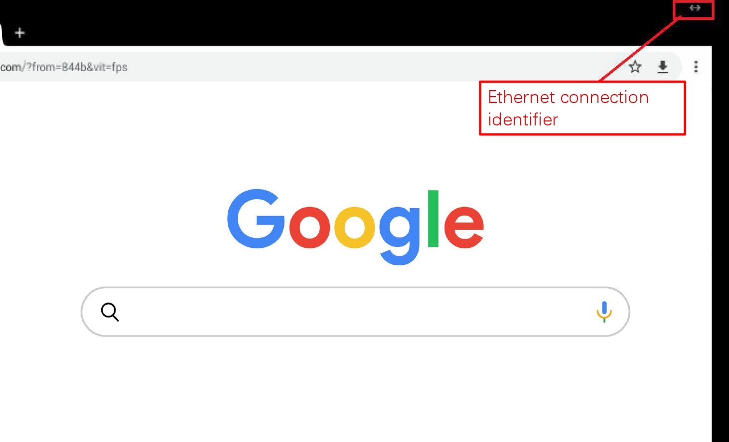
Directly plug in the network cable that can access the Internet, assign it to the address on the ANDROID interface, and you can access the Internet.
As shown in below picture:
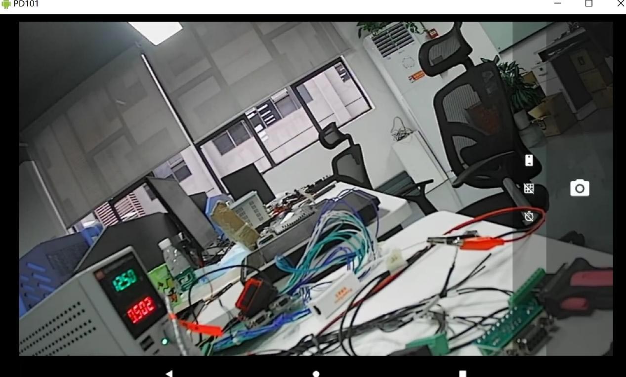
Directly insert the 720P CAMERA into the AHD1 interface corresponding to AHD, and the camera recording function can be realized in the native ANDROID CAMERA program. If you want to achieve multiple video simultaneous previews, you need to develop your own APK to achieve it.
T10 support built-in high-precision UM482 modules. (Please note: when the high-precision module is on working mode, the device working temperature is high, T10 is IP65 rated protection, the internal heat is mainly exported through the back metal block, please do not touch the metal block part by hand for long period)
T10 built-in UM482 differential positioning test steps:
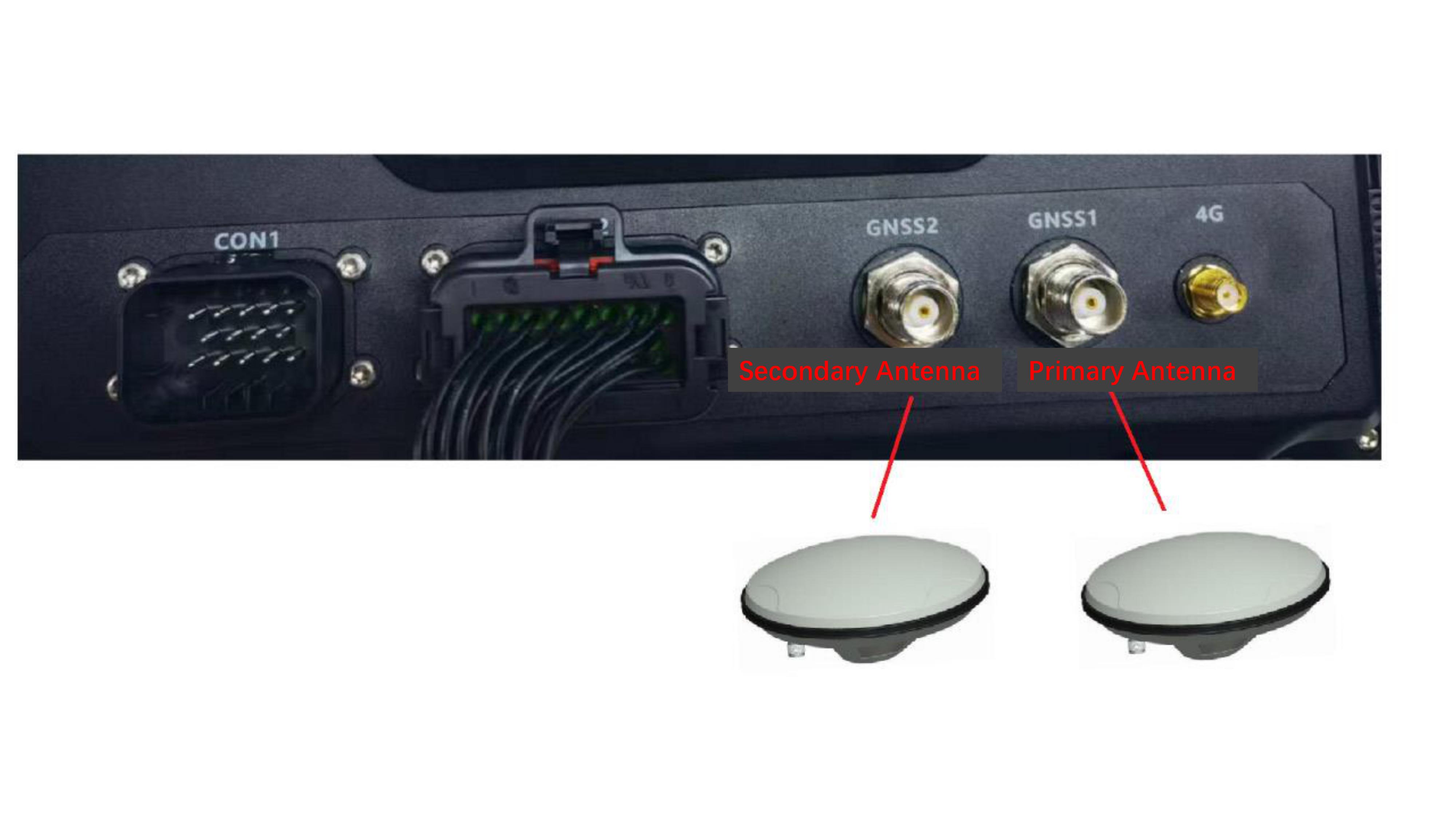
Step 1, connect the high-precision antenna to the TNC interface on the back of the T10, note: GNSS1 is connected to the main high-precision antenna, and GNSS2 is connected to the secondary high-precision antenna. If you are just positioning the application, you only need to connect a high-precision antenna to the TNC interface of the main antenna GNSS1.
Step 2. Under normal circumstances,when T10 is powered on, the UM482 has been powered on. At this time, you can use the built-in serial port tool to open the UM482 connected serial port node ttyS5, the baud rate set to 115200, you can see the NEMA statement output of um482, and from the GPGGA statement, you can see the positioning status, as shown in below picture:
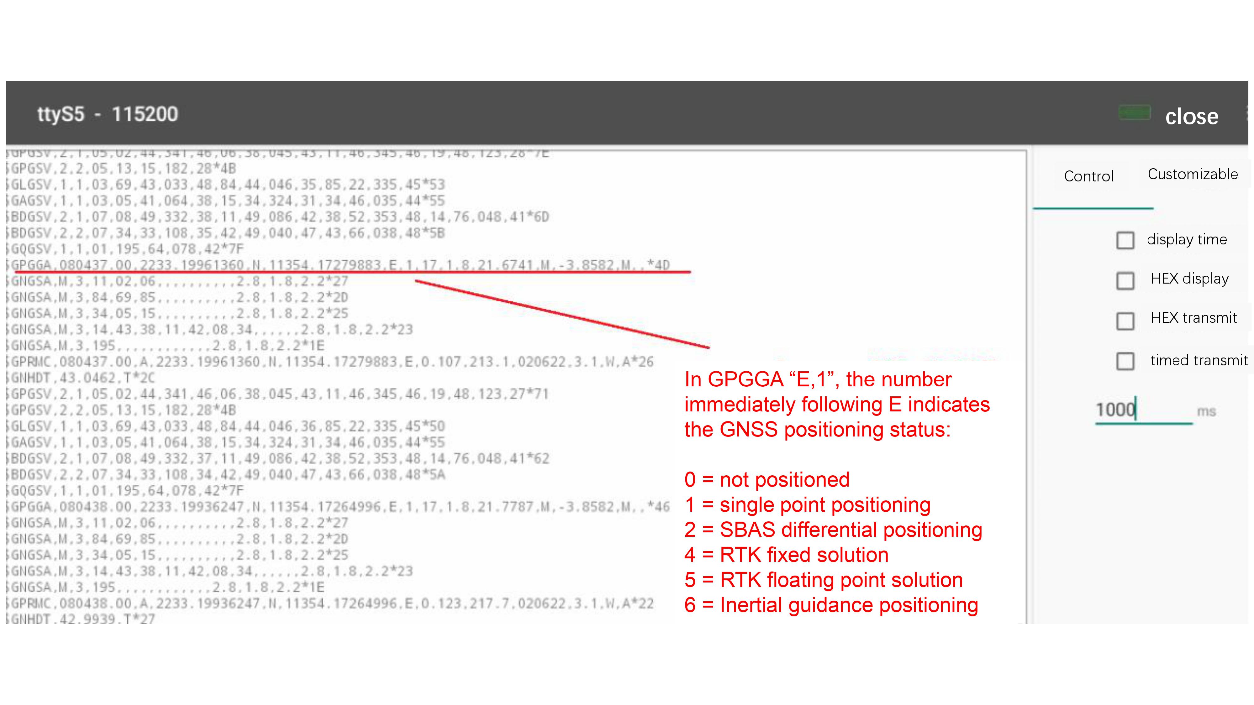
For information on the meaning of NEMA data, please refer to the following link: https://zhuanlan.zhihu.com/p/434992232
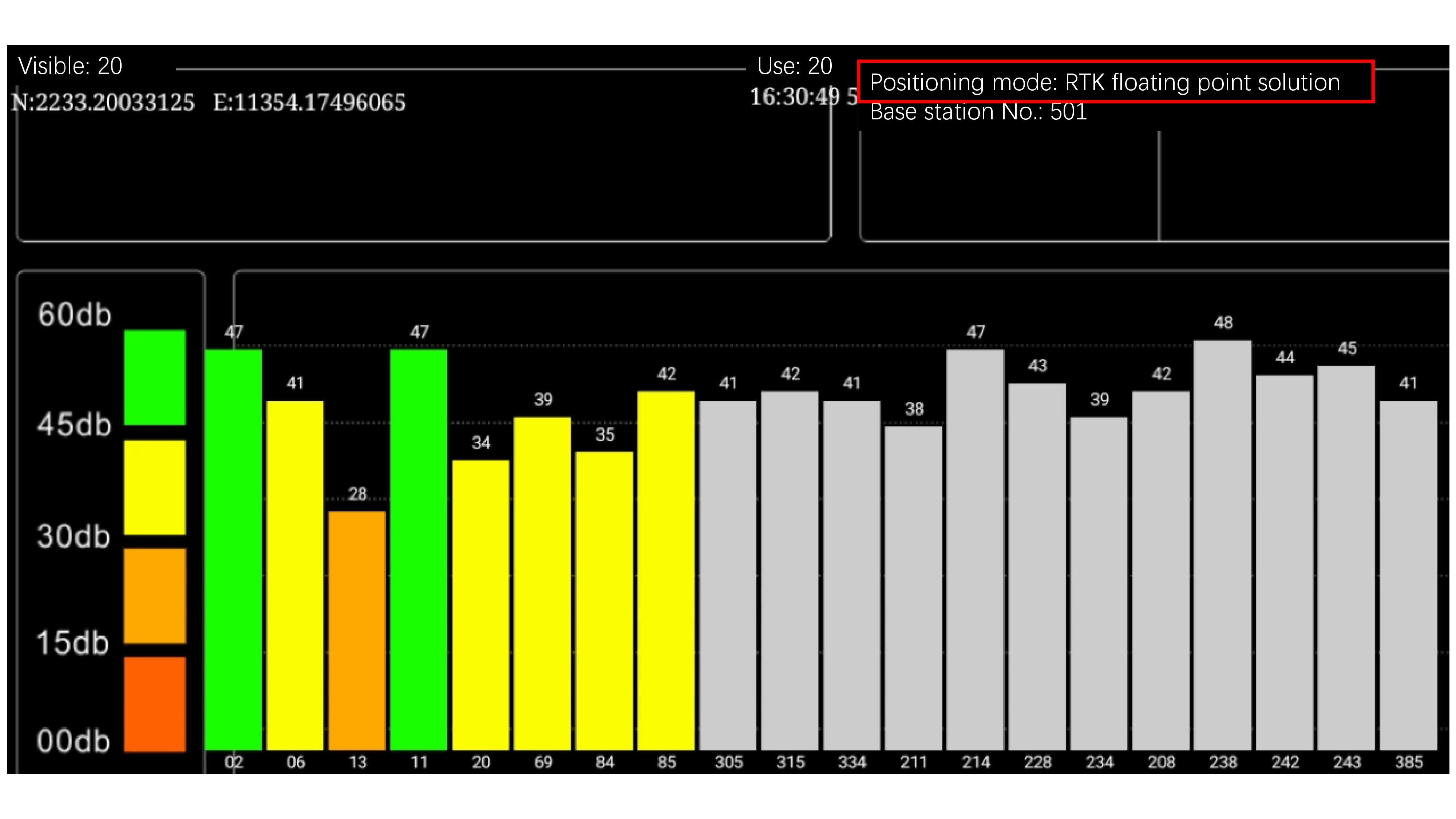
Step 3 The principle of UM482 to achieve differential positioning, is that the software through the protocol from the high-precision reference station to obtain differential data, the data is written to UM482. UM482 accepts the reference differential data, the internal algorithm calculating to obtain high-precision positioning. We have a simple DEMO to achieve this function, as shown in the following figure, showing that UM482 has been differentially positioned, you can contact our sales person for details.
